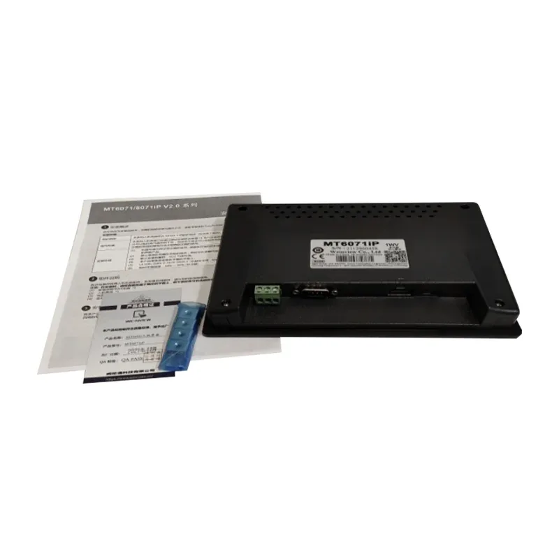
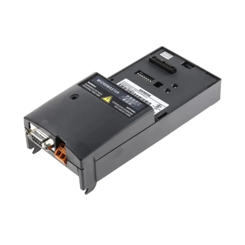
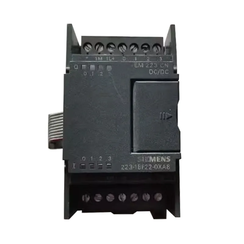
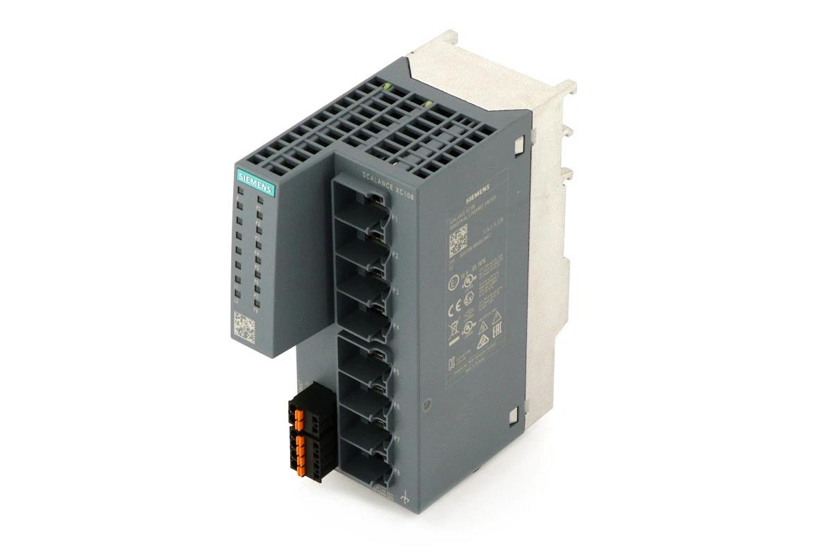
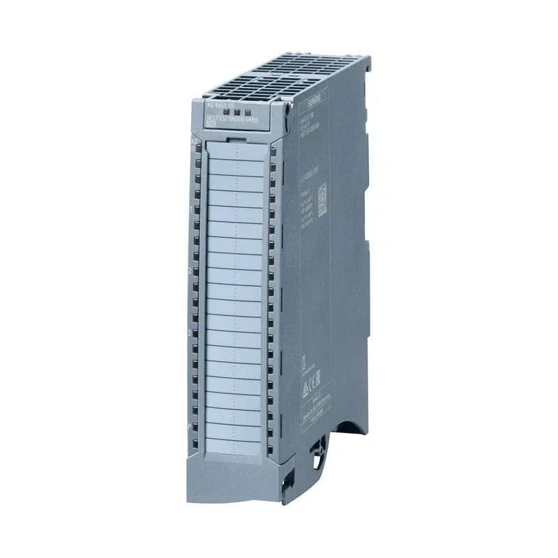
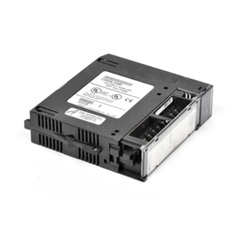
Replace the old armature module with the Siemens 6SE7028-2HF84-1HH1. The rotational speed of the Quanzhou Xin Yuan Technology wire drawing machine no longer drops. Previously, the low-frequency torque was weak, causing wire breakage. Now, it directly consumes the rated current, and there is no jolt during startup and drawing. If you want to buy, be sure to choose this board as it has stable voltage and accurate performance.
Hard indicators
The Siemens 6SE7028-2HF84-1HH1, as a vector control inverter, its core parameters directly determine the upper limit of the working conditions. The rated input is three-phase AC 380V - 480V, the rated output current is 71A, and it is suitable for 30kW conventional motor loads. The book-style structure size F, forced air cooling design, and the internal IGBT module has a withstand voltage level of 1600V. In actual measurement and control, the onboard tension and position loop response time is less than 5ms, and the V/f and closed-loop vector mode switching is smooth. For the direct drive of the spindle, it can output 150% of the rated torque at 0Hz, the speed ratio is 1:100, and the steady-state speed fluctuation rate at full load is ≤ 0.5%. The adjustable range of the output side carrier frequency is 2kHz - 16kHz. When the setting is higher than 8kHz, it needs to be used at a reduced capacity by 1.5%/℃. This is a hard boundary that is often overlooked.
Service life
The service life of the Siemens 6SE7028-2HF84-1HH1 device is directly limited by the aging rates of the DC bus capacitor and the IGBT module. Under the industrial benchmark of an environmental temperature below 40°C and an annual average operation of 8,000 hours, the expected lifespan of the electrolytic capacitor is 7-8 years; if it is continuously placed in a 50°C high-temperature chamber, the lifespan will be halved to around 4 years. In practice, the fan is the first vulnerable component. After continuous operation for 30,000 hours, the bearing wear will cause the cooling failure, triggering an over-temperature alarm. The lifespan of the IGBT is strongly related to the switching frequency and the depth of the load. Frequent emergency stops and rapid turns will cause a significant increase in thermal cycling stress, leading to cracking of the weld layer. It is recommended to clean the dust and measure the bus pre-charge resistance value every 2 years. When the cold-state equivalent series resistance deviates by 15% from the initial value, the entire board must be replaced.
Outbound Packaging Specifications
The outbound process strictly adheres to the dual standards of anti-static and anti-mechanical impact. The bare board must be vacuum-sealed in an anti-static shielding bag, with two bags of silica gel desiccant inside to control the humidity below 30%RH, to prevent the PCB from absorbing moisture and causing subsequent power-on leakage. The external part uses high-density EPE pearl cotton custom molds to suspend the interface terminals and power modules, protecting them from bending of the terminals or deformation of the heat sink during transportation.

Safety and Compliance
The Siemens 6SE7028-2HF84-1HH1 model complies with the CE low-voltage and electromagnetic compatibility directives, and has passed UL508C certification, meeting the IEC 61800-5-1 safety standard. During actual maintenance and replacement, compliance is not only judged by the certification, but also by the practical operation red line. Before assembly, it is necessary to confirm that the corresponding specification fast fuse and incoming line reactor have been installed on the incoming side to limit the short-circuit current. The grounding terminal must be independently grounded with a yellow-green wire, and the grounding resistance must not be mixed with the neutral line of the enclosure. During the restart test of the equipment, it is necessary to ensure that the DC bus voltage is confirmed to be reduced to below the safe voltage of 24V by the LED indicator light 5 minutes after power-off, otherwise, live operation is very likely to cause an arc injury or secondary breakdown of the control board.
Address
Huguang Road, Jinjiang City, Fujian Province, China
Tel